Resistance measurement could be several ohms or even 10 ohms. This may cause significate errors if the temperature reading. A 10 ohms difference can cause an error of 10/0,385 so approximately 26 °C in this case.
Wheatstone Bridge

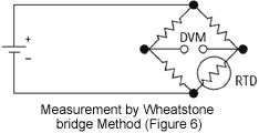
The bridge model shown here, is an indirect indication of the RTD resistivity. The bridge requires 4 parrallel branches; 1 exterior electrical source and 3 resistors with a zero temperature coefficient.
3 Wires Bridge
To avoid subjecting the 3 resistors to the same temperature of the RTD, we sperate them from the bridge with a pair of connection wires (Figure 7).

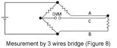
These wires recreate the problem that we have seen before: the resistance of the wires affects the temperature reading. This effect can be reduced to a minimum by employing the configuration of a 3 wires bridge (Figure 8). If wires A and B are the same length, their resistance effect will be annulled due to the fact that both are on an opposite side of the bridge. The third wire, C, is the measuring wire where there is no circulating current.

The Wheatstone bridge represented in Figure 8 creates a non linear relation between the resistance change and the change in tension in the bridge. This will require an additional equation to convert the tension measurement of the bridge into an RTD equivalent resistance.
4 Wires Measurement

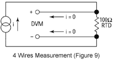
The best technique is to use a current source along with a remotely sensed digital voltmeter. Since no current can circulate in the tension measurement wires, there will be no drop in tension and therefore no error in resistance measurement. The tension read on the voltmeter is directly proportional to the resitance value of the RTD.
The three resitances of the bridge are replaced by a resitance of reference permitting to know, with precision, the generated current (Figure 9). The inconvenience is that it requires an additional wire than the 3 wire bridge. It is a small price to pay in order to obtain exact resitance measurements.
Even though it has excellent precision, the 4 wire resistance measurement, like all other measurements, will always be affected by errors and the results will be to try and minimize these errors by taking all the necessary precautions.

Resistance measurement could be several ohms or even 10 ohms. This may cause significate errors if the temperature reading. A 10 ohms difference can cause an error of 10/0,385 so approximately 26 °C in this case.
Wheatstone Bridge

The bridge model shown here, is an indirect indication of the RTD resistivity. The bridge requires 4 parrallel branches; 1 exterior electrical source and 3 resistors with a zero temperature coefficient.
3 Wires Bridge
To avoid subjecting the 3 resistors to the same temperature of the RTD, we sperate them from the bridge with a pair of connection wires (Figure 7).

These wires recreate the problem that we have seen before: the resistance of the wires affects the temperature reading. This effect can be reduced to a minimum by employing the configuration of a 3 wires bridge (Figure 8). If wires A and B are the same length, their resistance effect will be annulled due to the fact that both are on an opposite side of the bridge. The third wire, C, is the measuring wire where there is no circulating current.

The Wheatstone bridge represented in Figure 8 creates a non linear relation between the resistance change and the change in tension in the bridge. This will require an additional equation to convert the tension measurement of the bridge into an RTD equivalent resistance.
4 Wires Measurement

The best technique is to use a current source along with a remotely sensed digital voltmeter. Since no current can circulate in the tension measurement wires, there will be no drop in tension and therefore no error in resistance measurement. The tension read on the voltmeter is directly proportional to the resitance value of the RTD.
The three resitances of the bridge are replaced by a resitance of reference permitting to know, with precision, the generated current (Figure 9). The inconvenience is that it requires an additional wire than the 3 wire bridge. It is a small price to pay in order to obtain exact resitance measurements.
Even though it has excellent precision, the 4 wire resistance measurement, like all other measurements, will always be affected by errors and the results will be to try and minimize these errors by taking all the necessary precautions.


