RTD’s 101
History of RTD’s

During the same year that Seebeck discovered thermoelectricity, Humphrey Davy (1778-1829) would announce that metal resistivity had a clear dependance on temperature. Fifty years later, William Seamens used platinum in a resistance thermometer. This favourable choice standardized all future resistance thermometers with platinum being the key element for high precision temperature measurement. The Platinum Resistance Temperature Detector or PRTD is now used to measure from the triple point of hydrogen (-259,34°C) to the freezing point of silver (961,78°C). Platinum is particularly convenient for this type of temperature range,as it maintains an excellent stability which will hardly alter after repeat use.
In 1932, C.H. Meyers proposed construction of a Platinum Resistance Temperature Detector (RTD) composed of a platinum wire wrapped around a mica support core inside a glass tube. This type of construction minimizes the wire tension and maximizes resistance. Even thought it is a very stable assembly the thermal contact between the platinum and the measurement point is weak and a diminished temperature response time is the result. Due to the structure’s fragility, this type of RTD is used mainly in laboratories today.

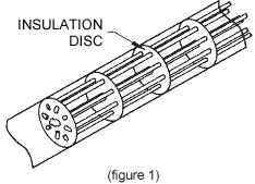
Another labaratory tool replaced Meyer’s concept. This “bird cage” element (Figure 1) was proposed by Evans and Burns. Resistance constraints provoked by time and temperature were reduced to a minimum and this style RTD became the labaratory norm. However, due to it’s fragile nature and sensitivity to vibrations, it was not suitable for industrial applications.
More solidly constructed RTDs are shown in figures 2, 3, and 4. A bifilament platinum wire is wound on a ceramic or glass core. This winding reduces magnetic induction and noise. Once the wire is wound on the core, the assembly is sealed by molten glass. As long as the dilation coefficient of the platinum wire and ceramic core are not exactly the same, the platinum wire’s dilation will result in a resistance change, sometimes consequenting in a permanent change of the wire’s resistance. Versions exist of RTDs that offer a compromise between the “bird cage” and the sealed spiral wound styles. This approach employs a rolled spiral of platinum wire wound on a ceramic cylinder and maintained by a

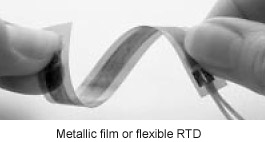
Modern fabrication techniques use a platinum or other metallic film deposited on a ceramic substrate that has been water jet cut, laser cut, and sealed. This film RTD offers a substantial savings in assembly time and high resistance for it’s size. Due to advanced technological fabrication, these devices are very small and have high thermal conductivity allowing a quick temperature change response time.
Film RTDs are less stable than wire filament wound RTDs but have a smaller size advantage, lower production time advantage, and are user friendly. These advantages have made this style RTD very popular and widely used.
RTD’s 101
History of RTD’s

During the same year that Seebeck discovered thermoelectricity, Humphrey Davy (1778-1829) would announce that metal resistivity had a clear dependance on temperature. Fifty years later, William Seamens used platinum in a resistance thermometer. This favourable choice standardized all future resistance thermometers with platinum being the key element for high precision temperature measurement. The Platinum Resistance Temperature Detector or PRTD is now used to measure from the triple point of hydrogen (-259,34°C) to the freezing point of silver (961,78°C). Platinum is particularly convenient for this type of temperature range,as it maintains an excellent stability which will hardly alter after repeat use.
In 1932, C.H. Meyers proposed construction of a Platinum Resistance Temperature Detector (RTD) composed of a platinum wire wrapped around a mica support core inside a glass tube. This type of construction minimizes the wire tension and maximizes resistance. Even thought it is a very stable assembly the thermal contact between the platinum and the measurement point is weak and a diminished temperature response time is the result. Due to the structure’s fragility, this type of RTD is used mainly in laboratories today.

Another labaratory tool replaced Meyer’s concept. This “bird cage” element (Figure 1) was proposed by Evans and Burns. Resistance constraints provoked by time and temperature were reduced to a minimum and this style RTD became the labaratory norm. However, due to it’s fragile nature and sensitivity to vibrations, it was not suitable for industrial applications.
More solidly constructed RTDs are shown in figures 2, 3, and 4. A bifilament platinum wire is wound on a ceramic or glass core. This winding reduces magnetic induction and noise. Once the wire is wound on the core, the assembly is sealed by molten glass. As long as the dilation coefficient of the platinum wire and ceramic core are not exactly the same, the platinum wire’s dilation will result in a resistance change, sometimes consequenting in a permanent change of the wire’s resistance. Versions exist of RTDs that offer a compromise between the “bird cage” and the sealed spiral wound styles. This approach employs a rolled spiral of platinum wire wound on a ceramic cylinder and maintained by a

Modern fabrication techniques use a platinum or other metallic film deposited on a ceramic substrate that has been water jet cut, laser cut, and sealed. This film RTD offers a substantial savings in assembly time and high resistance for it’s size. Due to advanced technological fabrication, these devices are very small and have high thermal conductivity allowing a quick temperature change response time.
Film RTDs are less stable than wire filament wound RTDs but have a smaller size advantage, lower production time advantage, and are user friendly. These advantages have made this style RTD very popular and widely used.


